Sitting at the MRI console, I reach for the Quality Control binder. I glance at the MRI Technologist who has a look of panic and fear on their face. It’s the kind of look that says, “Please don’t look in there, I know this isn’t going to be good.” I thumb through the pages and notice weeks of missing Quality Control and a smattering of failed results. You see, I’m a physicist. And in my time reviewing Quality Control, this is a common scenario. Balancing the competing priorities in an MRI department and Quality Control can become an afterthought. Compounding the issue is that much of the guidance for performing MRI Quality Control is written by physicists for other physicists. Not for technologists. So, what makes this guide any different? Well, before I went off to be a physicist, I was a technologist myself. And I quite enjoy putting on my technologist-hat from time to time. This guide is written with straightforward, step-by-step instructions and minimal physics jargon. And we might even have a little fun along the way. With that in mind, let’s get after it.
Key Point: A well-designed, well-documented, and reliably executed quality control (QC) program is essential to consistent production of high-quality MR images and is a key component of ensuring quality and safety in the MR Environment.
What Are The Requirements?
The requirements fall into 4 basic categories. The phantom, the frequency, the tests, and the documentation.
The Phantom
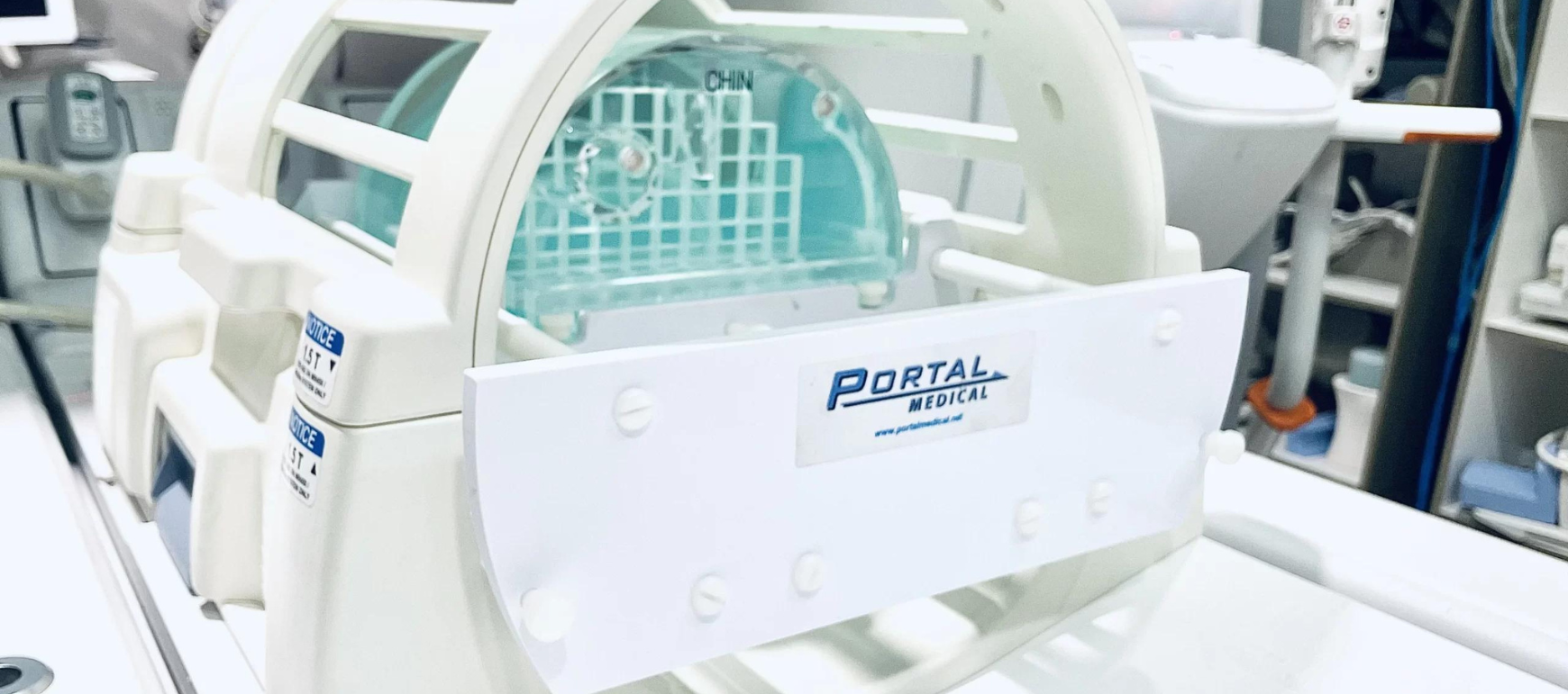
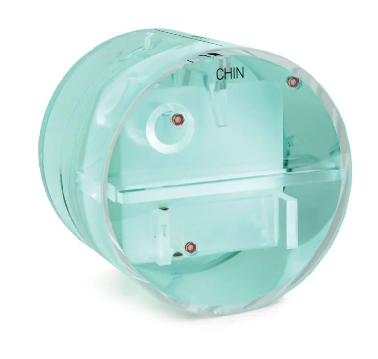
There are two phantoms that are approved by the American College of Radiology (ACR). There is the Large MRI Accreditation Phantom and the Small MRI Accreditation Phantom. The Large Phantom is used for whole body scanners while the Small Phantom is used for extremity scanners. This article will focus on the Large MRI Accreditation Phantom. And if you’re in need of purchasing a phantom, check out the phantoms offered by Supertech.
The Frequency
The ACR “strongly recommends” performing QC testing on a daily basis. That’s right, I said a daily basis. While I’m sure there are sites that perform MRI QC on a daily basis, I have not run into them. The minimum QC frequency is weekly, which is what the majority of sites are doing. Stick with a weekly QC schedule and you’ll be doing brilliantly.
Large MRI Accreditation Phantom
Pro-Tip: Schedule to perform your QC at the same time on Monday of each week. This way if scheduling issues arise, equipment fails, or you simply forget then you have additional days in the week in which you can still complete your QC requirements.
The Tests
We’re going to cover performing each test in detail in the following sections. But to give you a preview, the tests we’ll be performing are Table Position Accuracy, Center Frequency & Transmitter Gain, Geometric Accuracy, High Contrast Spatial Resolution, Low Contrast Detectability, and Artifact Evaluation. We’ll also need to perform the Visual Checklist, which has separate documentation.
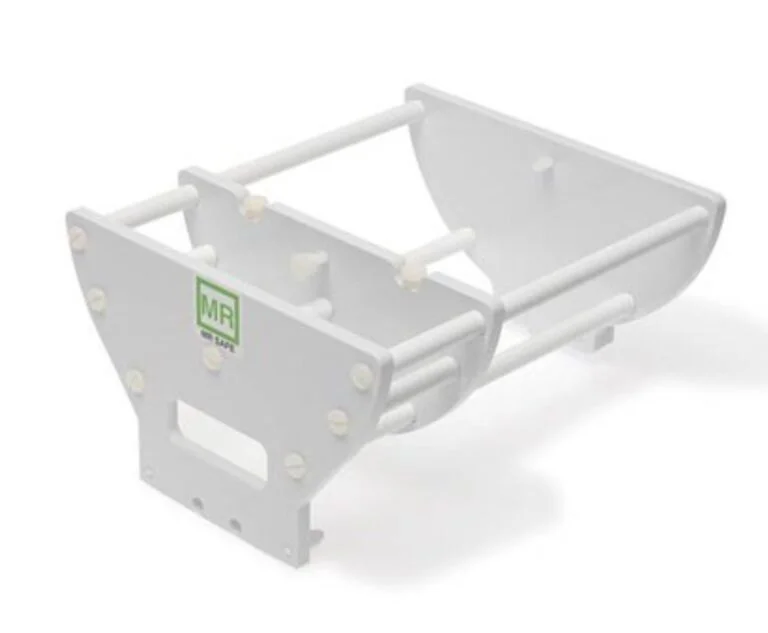
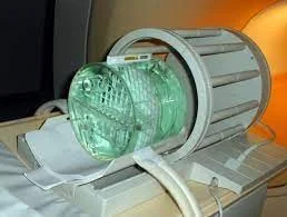
The large phantom should be positioned in the head coil so that it is in the center of the coil in the left/right and anterior/posterior direction. This is relatively easy to do using a phantom cradle for accurate and repeatable results. Alternatively, you can use a stack of computer paper to ensure the phantom is centered within the coil. Using the same stack of paper will be important to reproduce your results from week to week.
Phantom Cradle
ACR Phantom with Computer Paper
Use a level to ensure the phantom is level in all directions. Do this by placing the level on the front bar of the phantom and also on the top of the phantom.
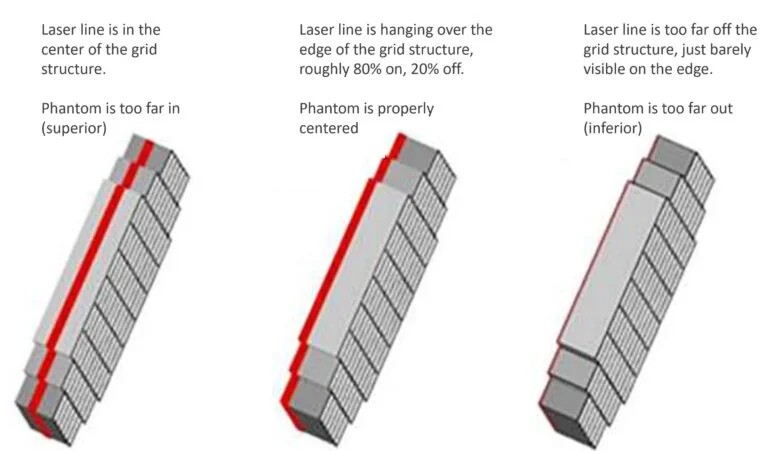
Move the phantom into position within the scanner using the laser to complete the positioning. The laser should be positioned so that 80% of the laser is on the grid structure and 20% is off the grid structure. How do you determine if 80% of the laser is on the grid? Just aim for having the majority of the laser line on the grid and a little bit off of the grid and you’ll be fine.
Send the phantom to isocenter and you’re now ready to scan!
Scanning The Phantom
A three-plane localizer should be used to ensure the phantom is properly positioned, followed by the acquisition of a sagittal localizer. The ACR sagittal localizer sequence should use the following parameters.
Sagittal Localizer Imaging Parameters
Pulse Sequence
Spin Echo
TR
200 ms
TE
20 ms
FOV
25 cm
Number of Slices
1
Slice Thickness
20 mm
Slice Gap
N/A
NEX (Averages)
1
Matrix
256 x 256
Scan Time
51-56 seconds
Table Position Accuracy
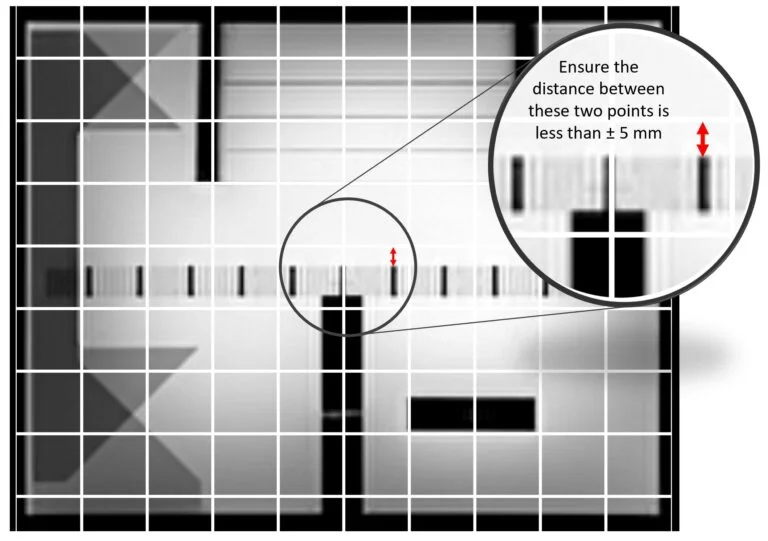
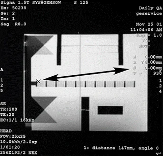
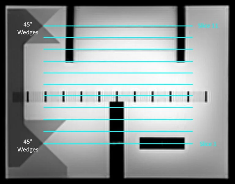
After acquiring the sagittal localizer, review the image. You’ll need to make measurements on the Sagittal Localizer to verify the Table Position Accuracy. Each manufacturer is slightly different, but the principle is the same. Turn on the “Grid” function and you’ll have a horizontal line and a vertical line superimposed on the Sagittal Localizer. This is your X and Y axis. In this case, we don’t care about the Y axis. On the image, take a measurement from the X axis to the top of the grid structure in the phantom. The grid structure in the phantom is denoted by the 11 little vertical black lines on the image.
Another option may be to turn on the cursor and hover over the image at the top edge of the grid structure. In the example below, we can see the cursor is at a position of S 0.00 mm. This means the top edge of the grid structure is exactly at isocenter.
Table Position Accuracy Example with Grid Turned On
Table Position Accuracy Example with Cursor
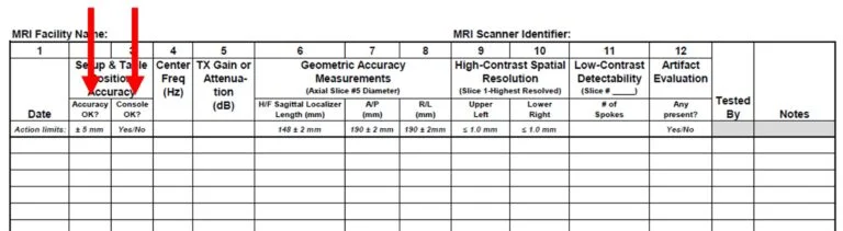
Action Criteria: The top edge of the grid should be within ± 5mm of isocenter.
If the location of the top edge of the grid structure is within ±5 mm of isocenter, enter “YES” in the column designated “Accuracy OK?”
If the computer booted without a problem and the scanner interface works properly, enter a “YES” in the column designated as “Console OK?”
The Center Frequency and Transmitter Gain of the ACR T1 protocol must be documented on the QC Form. The ACR T1 protocol should use the following parameters.
ACR T1 Imaging Parameters
Pulse Sequence
Spin Echo
TR
500 ms
TE
20 ms
FOV
25 cm
Number of Slices
11
Slice Thickness
5 mm
Slice Gap
5 mm
NEX (Averages)
1
Matrix
256 x 256
Scan Time
~ 2:10
The ACR T1 protocol should be used to scan the phantom in 11 slices. The scan range should be placed right between the two 45⁰ wedges placed in the phantom. See figure to the right.
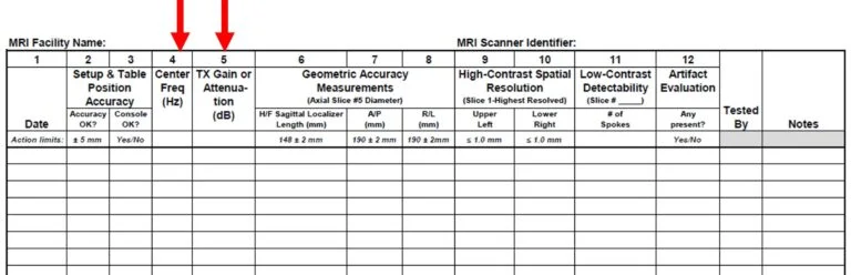
Action Criteria: The Larmor Frequency is about 64 MHz for a 1.5T scanner and 128 MHz for a 3T scanner. This means the action limit for 1.5T scanners is a week to week change of ± 128 Hz. The action limit for 3T scanners is a week to week change of ± 256 Hz. Recording the last 4 digits of the Center Frequency in Hz is fine. For Transmit Gain, we typically set a baseline by taking an average after a series of 10 measurements and set action limits of ±20% from baseline. You should consult with your medical physicist when setting the baseline values and action limits for the Center Frequency and Transmit Gain.
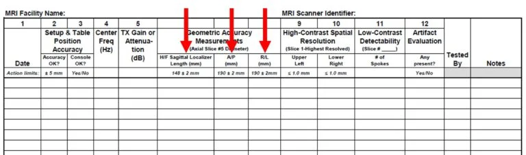
Geometric Accuracy is measured using the Sagittal Localizer as well as Slice 5 from the ACR T1 series. It’s important to set the window width and level the same way each time. The ACR’s method for doing this is a little complicated, so we’re going to break this down.
Step 1: Set the window width to 0 or 1. Step 2: Adjust the window level until one half of the image is white and the other half is black. It’s OK to estimate here. Note the window level setting. Step 3: Now adjust the window width to the same value. We want the window width and window level to be equal. Step 4: Finally, reduce the window level value by half.
Step 2 - Half White / Half Black
Example: Bring your window width to 0. Adjusting the window level until half the image is white and half is black you note the window level is at ~1400. Now you adjust the window width to also be ~1400. Finally, take you window level to ~700 and you’re ready to make your measurements!
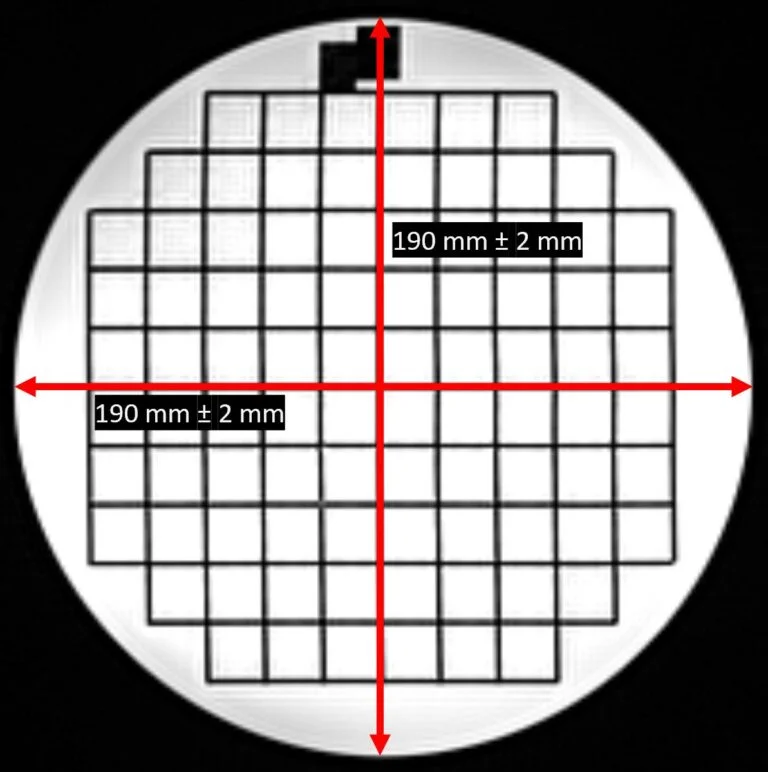
Proceed with making geometric accuracy measurements on the image(s). For the Sagittal Localizer image, you’ll make a measurement in the Head/Foot direction (top to bottom). Then for Slice 5 on the ACR T1 protocol, you’ll make measurements in the Anterior/Posterior direction and in the Right/Left direction.
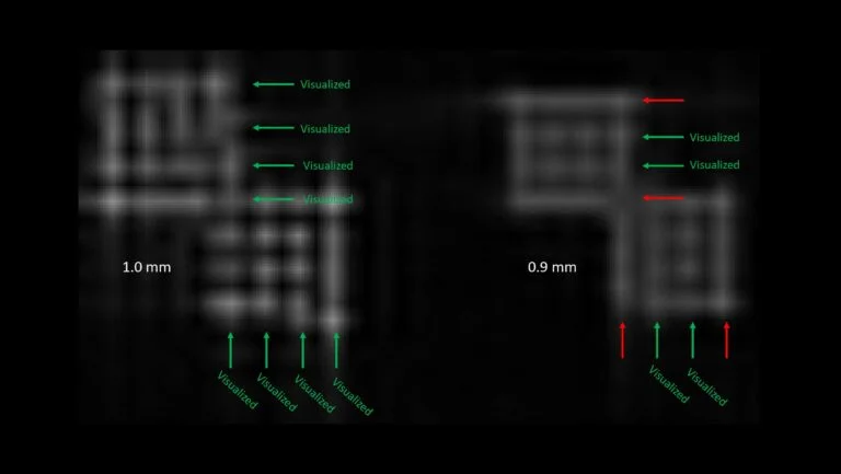
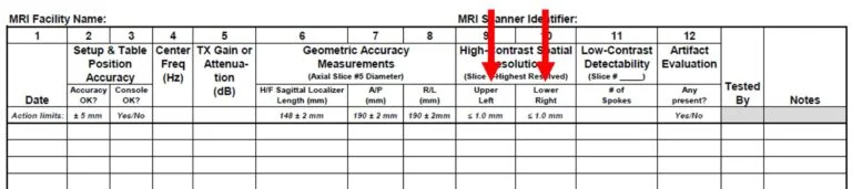
Now we’re ready to move on to High Contrast Spatial Resolution. We’re going to simplify this and just call this resolution. Resolution is measured using Slice 1 of the ACR T1 images series. The resolution insert consists of three resolution targets with an upper-left (UL) and lower-right (LR) and share one hole in common at the corner where they meet. The diameter of the left target is 1.1 mm, the center target is 1.0 mm, and the right target is 0.9 mm.
High Contrast Spatial Resolution Targets & Hole Sizes
Zoom in on the image so that you can see the resolution targets. Then adjust the window width and level until the holes in the resolution insert can best be seen. The upper-left array is used to assess resolution in the horizontal direction. To do this, look at the rows in the upper-left array to see if all four holes in any single row are distinguishable from one another. The smallest target with an entire row as distinguishable should be recorded as the resolution for the upper-left (UL) array.
Repeat the same steps for the lower-right array in the vertical direction by looking at the columns in the lower-right array to see if all four holes in any single column are distinguishable from one another. The smallest target with an entire column as distinguishable should be recorded as the resolution for the lower-right (LR) array.
So what exactly does distinguishable mean? To be observed as distinguishable, the image intensity does not need to drop to zero between the holes; that would not be normal. However, the window width and level setting should allow all four holes in at least one row (UL) or one column (LR) as recognizable points of brighter signal intensity than the spaces between them. When the holes size is comparable to the resolution in the images, there is a tendency for groups of two or more holes in a row or column to blur together and appear as a single irregularly shaped spot of signal. In this case the holes in that row or column would be considered unresolved.
Let’s look at an example…
High Contrast Spatial Resolution Example
In the example above we can see every row in the upper-left array and every column in the lower-right array for the 1.0 mm targets. When we look at the 0.9 mm targets, we can distinguish 2 rows in the upper-left array and 2 columns in the lower-right array. Because we only need to see at least one row and one column to call a target visualized, we would enter 0.9 mm into our spreadsheet for Columns 9 and 10.
Action Criteria: You should be able to visualize at least the 1.0 mm target.
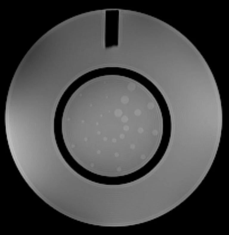
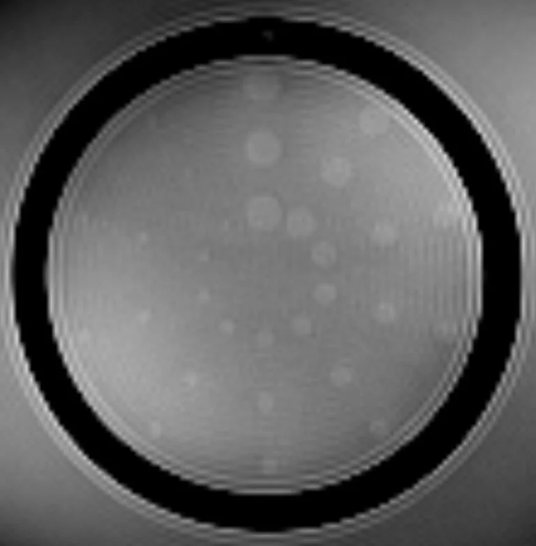
Low Contrast Detectability (LCD) is evaluated in slices 8-11 of the ACR T1 series. In each slice, the low-contrast objects appear as a row of small disks radiating from the center of the phantom like spokes on a wheel. Each spoke is made up of 3 discs, and there are 10 spokes in each circle. The contrast values increase as you go from slice 8 to slice 11. The measurements for this test consists of counting the number of complete spokes seen in a designated axial slices. Which slice is the designate slice? The most appropriate slice for evaluation should be set by your medical physicist. However, general guidance for determining the appropriate slice is to use the lowest contrast slice where some spokes are not visualized. This is often Slice 8.
Display the slice to be scored using a window width and level setting for best visibility of the low contrast objects. Count the number of spokes seen beginning with the 12 o’clock position and working clockwise. The number of complete spokes where all three discs are discernible from background is the score for that slice.
Low Contrast Objects
Magnified Low Contrast Objects
Action Criteria: The action criteria for low contrast should be set by your medical physicist.
Artifact Evaluation
Artifact Evaluation should be performed on each slice of the ACR T1 series. The window width and level should be adjusted so that a full range of pixel values can be observed in the image; the image should have varying levels of gray and should not be all black or all white. When evaluating the phantom for artifacts, you should make sure
The phantom appears circular, not elliptical or otherwise distorted.
There are no ghost images of the phantom in the background or overlying the phantom image.
There are no streaks or artifactual bright or dark spots in the image.
There are no unusual or new features in the image.
Action Criteria: The images should be free of artifacts. If you have artifacts in the image, you should contact your service engineer or medical physicist.
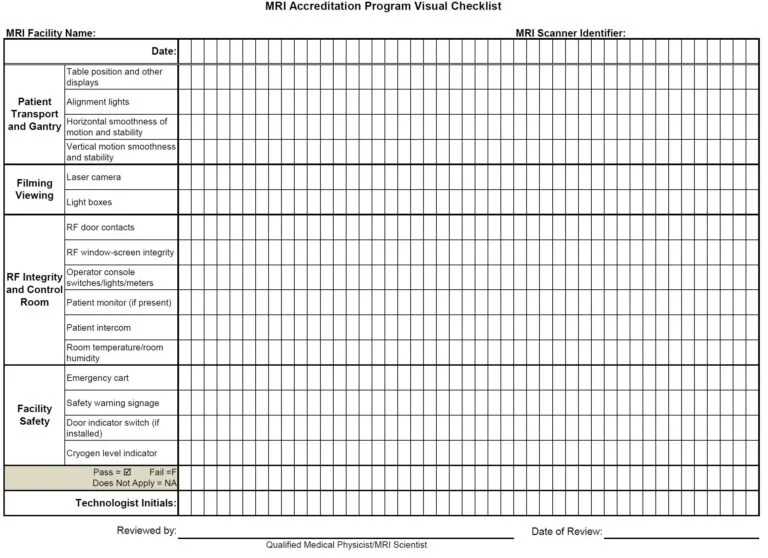
MRI Accreditation Program Visual Checklist
On a weekly basis, the MRI Visual Checklist should be completed to verify the MRI system patient bed transport, alignment and system indicator lights, RF room integrity, emergency cart, safety lights, signage, and monitors are present and working properly and are mechanically and electrically stable.
Documentation is performed on a separate Visual Checklist sheet. You can download a copy here.
MRI Accreditation Program Visual Checklist
Each of the items listed in the visual checklist should pass or receive a checkmark. Items not passing the visual checklist should be replaced or corrected immediately. Items missing from the room should be replaced immediately. Malfunctioning equipment should be reported to the MRI service engineer for repair or replacement as soon as possible.
Wrapping Up
If you’ve made it this far, congratulations! You’ve successfully made it through all of the required steps for performing MRI Quality Control. A couple of key takeaways
Perform MRI QC on a weekly basis
Follow the steps in this guide
Document your results
And that’s it. You’re now well on your way to a well-executed quality control program and passing all of your ACR inspections like a breeze!